Flashing Firmware
Binding USB Ports
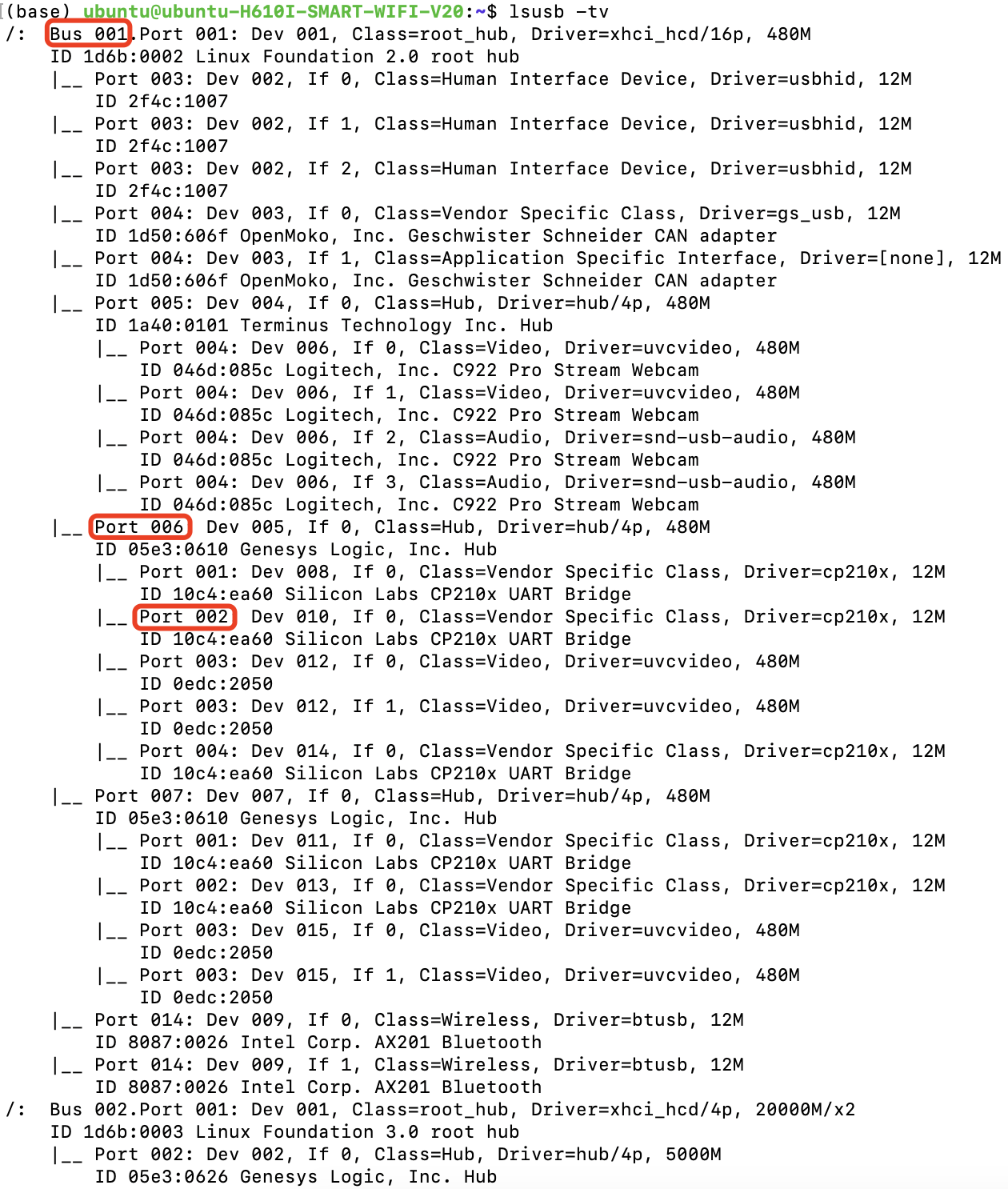
The USB device’s name on Linux changes after each reboot, so we need to fix it. We bind USB devices via KERNELS. For example, the KERNEL value of the /dev/video0 device can be obtained by udevadm info —-name=/dev/video0 --attribute-walk | grep KERNELS command or by lsusb —tv.
For example, in this output, 1-6.2:1.0 represents the device tty_puppet_left:
Please follow the format in the 99-astra-fixed-port.rules file to bind the USB device in /etc/udev/rules.d/99-astra-fixed-port.rules:
Configure the udev rules for the ODrive:
sudo bash -c "curl https://cdn.odriverobotics.com/files/odrive-udev-rules.rules > /etc/udev/rules.d/91-odrive.rules"
Apply the modified configuration:
sudo udevadm control --reload && sudo udevadm trigger
Flashing the Firmware of the Arm Controller
Clone the AstraFirmwares project and its subprojects:
git clone --recurse-submodules anonymized_url
Open the arm controller’s firmware source code directory using VSCode/Cursor:
code AstraFirmwares/AstraArmController
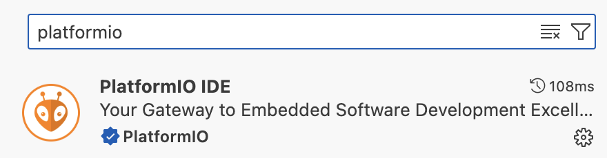
Install the PlatformIO plugin:
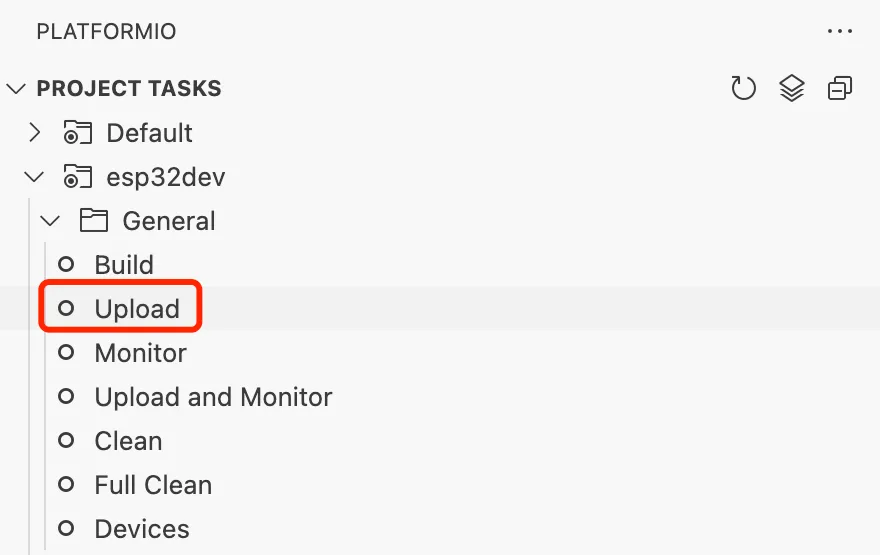
Compile the project and flash the firmware of the right arm controller:
Modify upload_port=/dev/tty_puppet_left in the platformio.ini file, save it, do the same as for the right arm, compile the project, and flash the firmware for the left arm controller.
Flashing the Firmware of the Lift Controller
Use VSCode/Cursor to open the firmware source code directory of the lift controller:
code AstraFirmwares/AstraLiftController
Compile the project, and first flash the firmware of the right lift controller, similar to the arm controller.
Modify the main.cpp:
- #define STEPPER_CORRECT_DIR(x) ((x)) // Normal (right)
- // #define STEPPER_CORRECT_DIR(x) (-(x)) // Reversed (left)
+ // #define STEPPER_CORRECT_DIR(x) ((x)) // Normal (right)
+ #define STEPPER_CORRECT_DIR(x) (-(x)) // Reversed (left)
Modify upload_port=/dev/tty_puppet_lift_left in platformio.ini file, save the compiled project, and flash the firmware of the left lift controller.
Flashing the Firmware of the Head Controller
Open the firmware source directory of the head controller using VSCode/Cursor:
code AstraFirmwares/AstraHeadController
Compile the project and flash the firmware for the head controller.
Flashing the Firmware of the Pedal Controller
Use VSCode/Cursor to open the firmware source directory for the pedal controller:
code AstraFirmwares/AstraPedalController
Since the pedal controller is only temporarily connected to the onboard computer for flashing the firmware, you will need to find the file path to the pedal controller by plugging and unplugging the device in the /dev directory. Add upload_port=/dev/ttyUSB{YOUR_PATH_HERE} to the end of the platformio.ini file, save the compilation project, and flash the firmware for the pedal controller.
Configuring the ODrive Controller
Updating the ODrive Controller version
First, make sure the ODrive firmware is at the latest open source version v0.5.6. If not, please update the firmware to version 0.5.6. Please refer to ODrive Documentation (or use STM DfuSe to flash in ODrive Releases)
Install ODrive Tool
Install the ODrive Tool:
pip install odrive
Run the ODrive Tool, which will connect to the ODrive via the USB CDC port (not CAN):
odrivetool
First, clean up the existing configuration and wait for the ODrive to automatically reboot and reconnect:
odrv0.erase_configuration() # with reboot
Configure Motor Parameters
Configure the motor parameters:
# lease the protection
odrv0.config.dc_max_negative_current = -5.0 # charging current
odrv0.axis0.motor.config.current_lim = 20

# set motor poles and hall encoder
odrv0.axis0.motor.config.pole_pairs = 10 # the motor has 10 poles
odrv0.axis0.encoder.config.mode = ENCODER_MODE_HALL # use ABC(UVW) hall encoder
odrv0.axis0.encoder.config.cpr = 60 # pulses per rev (6 * pole num)
odrv0.axis0.encoder.config.bandwidth = 50

odrv0.axis0.motor.config.resistance_calib_max_voltage = 5 # voltage for calibration
odrv0.axis0.encoder.config.calib_range = 0.1
odrv0.axis0.encoder.config.calib_scan_distance = 150
odrv0.axis0.motor.config.current_control_bandwidth = 1000 # related to the PD parameter of the current loop. the larger it is, the "harder" the current loop is.

# ignore illegal_hall_state error
odrv0.axis0.encoder.config.ignore_illegal_hall_state = True
Set up another motor in the same way:
odrv0.axis1.motor.config.current_lim = 20

odrv0.axis1.motor.config.pole_pairs = 10
odrv0.axis1.encoder.config.mode = ENCODER_MODE_HALL
odrv0.axis1.encoder.config.cpr = 60
odrv0.axis1.encoder.config.bandwidth = 50

odrv0.axis1.motor.config.resistance_calib_max_voltage = 5
odrv0.axis1.encoder.config.calib_range = 0.1
odrv0.axis1.encoder.config.calib_scan_distance = 150
odrv0.axis1.motor.config.current_control_bandwidth = 1000

odrv0.axis1.encoder.config.ignore_illegal_hall_state = True
Wait 1 second for the communication between the upper and lower computer to complete, save the configuration, and reboot:
# wait for 1 second

odrv0.save_configuration()
odrv0.reboot()
Calibrate the Encoder
The encoder can then be calibrated:
odrv0.axis0.requested_state = AXIS_STATE_FULL_CALIBRATION_SEQUENCE # start calibration
A beep will come from the driver board, please make sure that the motor is not touching the ground. After that, the motor will rotate a few times by itself, wait for the motor to stop, save the calibration parameters, and restart:
odrv0.axis0.encoder.config.pre_calibrated = True
odrv0.axis0.motor.config.pre_calibrated = True

# wait for 1 second

odrv0.save_configuration()
odrv0.reboot()
Follow the same way to calibrate another motor:
odrv0.axis1.requested_state = AXIS_STATE_FULL_CALIBRATION_SEQUENCE # start calibration

# wait until motor stop

odrv0.axis1.encoder.config.pre_calibrated = True
odrv0.axis1.motor.config.pre_calibrated = True

# wait for 1 second

odrv0.save_configuration()
odrv0.reboot()
Setting the Motion Mode
Set the motor to position mode and enable trapezoidal acceleration and deceleration:
# position mode and tune the parameters
odrv0.axis0.controller.config.control_mode = CONTROL_MODE_POSITION_CONTROL
odrv0.axis0.controller.config.pos_gain = 20
odrv0.axis0.controller.config.vel_gain = 0.10
odrv0.axis0.controller.config.vel_integrator_gain = 0

# trapezoidal acceleration and deceleration:
odrv0.axis0.controller.config.input_mode = INPUT_MODE_TRAP_TRAJ
odrv0.axis0.controller.config.vel_limit = 20
odrv0.axis0.trap_traj.config.vel_limit = 20
odrv0.axis0.trap_traj.config.accel_limit = 1
odrv0.axis0.trap_traj.config.decel_limit = 1

# # start closed loop control
# odrv0.axis0.requested_state = AXIS_STATE_CLOSED_LOOP_CONTROL
# odrv0.axis0.config.startup_closed_loop_control = True

# # test
# odrv0.axis0.controller.input_pos = 5
Set another motor in the same way:
# position mode and tune the parameters
odrv0.axis1.controller.config.control_mode = CONTROL_MODE_POSITION_CONTROL
odrv0.axis1.controller.config.pos_gain = 20
odrv0.axis1.controller.config.vel_gain = 0.10
odrv0.axis1.controller.config.vel_integrator_gain = 0

# trapezoidal acceleration and deceleration:
odrv0.axis1.controller.config.input_mode = INPUT_MODE_TRAP_TRAJ
odrv0.axis1.controller.config.vel_limit = 20
odrv0.axis1.trap_traj.config.vel_limit = 20
odrv0.axis1.trap_traj.config.accel_limit = 1
odrv0.axis1.trap_traj.config.decel_limit = 1

# # start closed loop control
# odrv0.axis1.requested_state = AXIS_STATE_CLOSED_LOOP_CONTROL
# odrv0.axis1.config.startup_closed_loop_control = True

# # test
# odrv0.axis1.controller.input_pos = 0
Save the parameters and restart:
# wait for 1 second

odrv0.save_configuration()
odrv0.reboot()
Debugging Tips
If you find that your version of ODrive suddenly doesn’t work, you can dump the current error status:
# for any errors
dump_errors(odrv0)
odrv0.clear_errors()
ODrive also provides a live plot tool:
# for live plot
import matplotlib; matplotlib.use('TkAgg');
start_liveplotter(lambda: [
    odrv0.axis0.encoder.count_in_cpr,
    odrv0.axis0.encoder.pos_estimate_counts,
])